

Why 3D scan artefacts?
Computational methods are revolutionising the types of analysis that archaeologists can carry out. Taking measurements is one of the fundamental ways in which we characterise and compare artefacts, but it can be hard to fully capture an artefact’s shape using traditional methods. Added to this is the practical problem that some hand-held tools, like goniometers for measuring angles, are difficult to use accurately.
Analysis
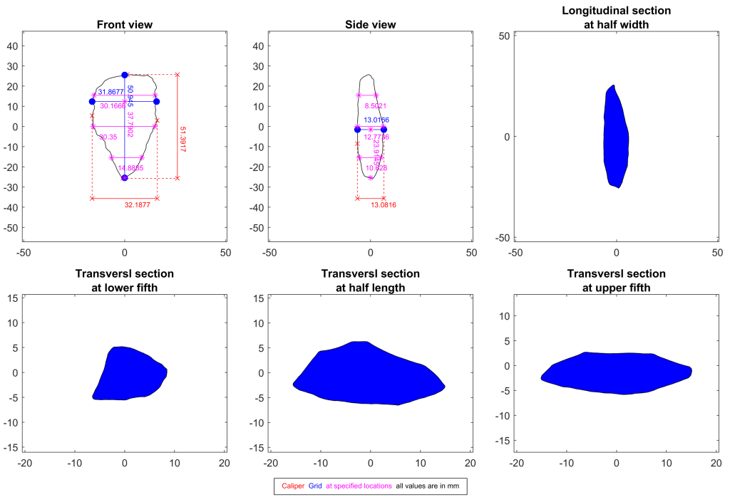
3D models allow a huge range of complex methods to be applied, with Geometric Morphometrics (GM) being one powerful tool for analysing shape. Accurate measurements can also be taken from 3D models.
Curation
For surface artefacts that are left in the field like ours, 3D models create a valuable archive for re-examining artefacts you don’t physically have access to. While virtual artefacts are not the same as holding the real thing, some archaeological research of the future could lie in digital archives rather than visiting museum collections.
Education
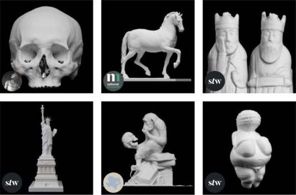
3D models can be printed as replica artefacts for teaching and public outreach. There are many types of 3D printing using various materials (plastic thread, powder, resin) with different properties and price points. Check out Scan the World for free models of artefacts that you can download and print yourself! 3D printed artefacts are an important component in our Tankwa Toolbox project. The Museum of Stone Tools is another amazing resource for viewing and downloading 3D models of stone tools online with great accompanying information to learn more.

How does 3D scanning work?
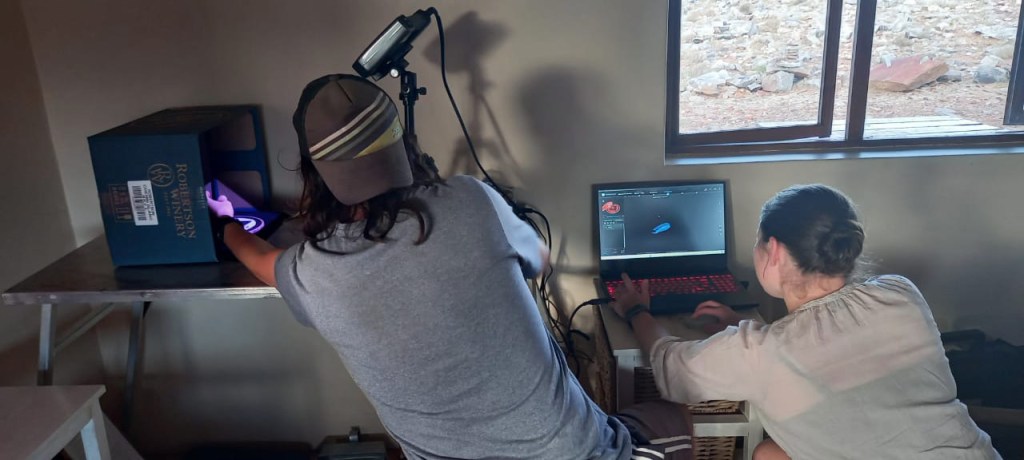
There are scanners available that use a range of different methods (e.g. lasers, x-rays, photographs) to capture 3D data to build a digital model that exactly replicates the original. The scanner that we used, the Einscan Pro, uses structured light.
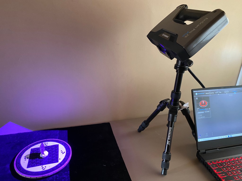
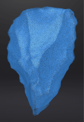
The scanner projects a striped pattern of light onto the surface of the object being scanned. Two cameras on either side of the projector then examine the projected light pattern and use trigonometry to calculate the distance of every point in its view. This only captures the face of the object that is facing the scanner cameras, so a series of scans from different viewpoints are needed to build up a cloud of measured points that captures your object in three dimensions.

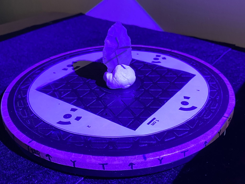
We used a manual turntable (more fieldwork-friendly than the automatic motorised turntable that comes with the scanner) marked with ‘stops’ at different points around its 360 degrees so that we could systematically build up our model. As well as fully rotating the object on this plane, you also need to reorient the object so its lower face is on top in order to cover its whole surface. To get your different orientations to align correctly, it helps to begin your new orientation with a surface you have already scanned so the software has known points to map your new scans onto.
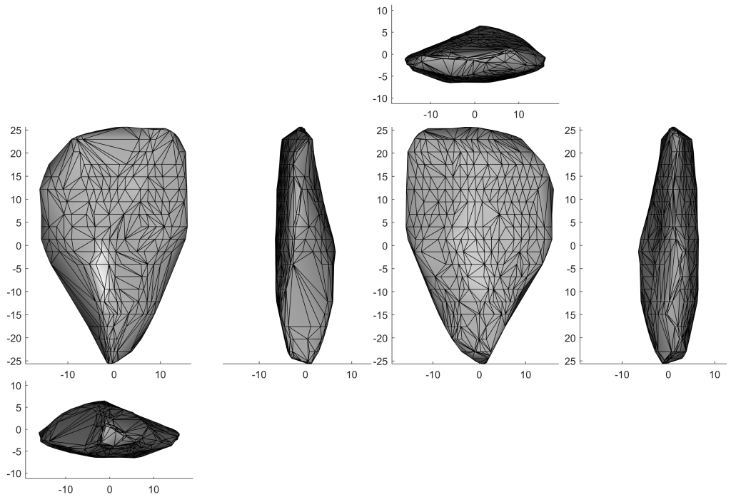
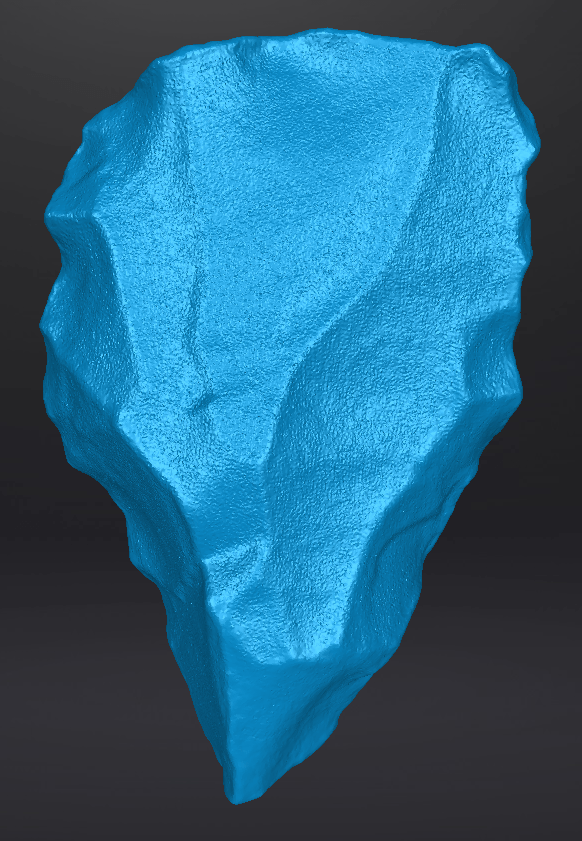
Once the point cloud is complete, you can process the model by creating a mesh – this effectively joins the dots between the points to create a surface of triangles. This is your 3D model! As well as taking measurements from your model, there are a host of post-processing tools you can use for analysis or to render a model for 3D printing.
How easy is 3D scanning?
With the Einscan, the process is relatively straightforward as the Shining 3D software automatically aligns your different scans so you see your model building up with each one. This is simpler than some other scanners where you have to manually match fixed points between scans to stitch them together. However, there are various small problems that can hinder the process.
Troubleshooting 1: dark or shiny surfaces
A frequent issue we encountered was scanning very dark coloured or shiny artefacts. The scanner fires pulses of light at the object to build the point cloud, meaning that if a material is black (which absorbs light) or shiny (which reflects light), the scanner can’t ‘see’ it and so you get holes in your model. Our fieldwork hack alternative to using expensive scanning spray was to lightly brush baby powder on the artefact surface, making it lighter and matt for the scanner to capture more easily. The powder then brushes off causes no lasting damage to the artefact.

Troubleshooting 2: scan alignment
Another mishap we faced was the artefact moving during the light capture process. We used mouldable sticky-tack putty to hold our artefacts in place on the turntable, but high temperatures meant sometimes the putty would melt and our object would slump, creating a misaligned scan. While sometimes the scan software could self-correct a few scans later, the only reliable fix was to pay attention and catch a problem scan as soon as possible (not always easy when scan fatigue set in after hours of repetitive work). The Einscan software interface allows you to view scans individually so it is easier to pick up any problem scans and edit or delete them, rather than having to start again from scratch. Unfortunately we aren’t aware of any ‘undo’ function in the Shining 3D workflow to go back to a previous alignment, and the only alternative is to manually select and match known points (which is fiddly so we opted for rescanning).
Troubleshooting 3: acute-angled edges
Perhaps the most frustrating problem was capturing very fine edges on flakes. Cores were quite easy to scan because they had chunky geometries and large surfaces for the projected light to hit, but flakes and points with acute-angled edges are trickier. We found that the manual turntable made this easier to troubleshoot than using the automatic turntable since you can rotate the artefact in smaller increments over its steep edges. There is no fail-safe method but we found that positioning a flake on its side (with one of its lateral edges in the putty) and rotating from the dorsal surface towards the platform gave a greater number of stable points in the point cloud for the edges and the distal tip than starting with other orientations. Reapplying baby powder to the edges between scans also helped the scanner to pick them up. Ultimately, a lot of patience pays off in scanning these problem pieces slowly.
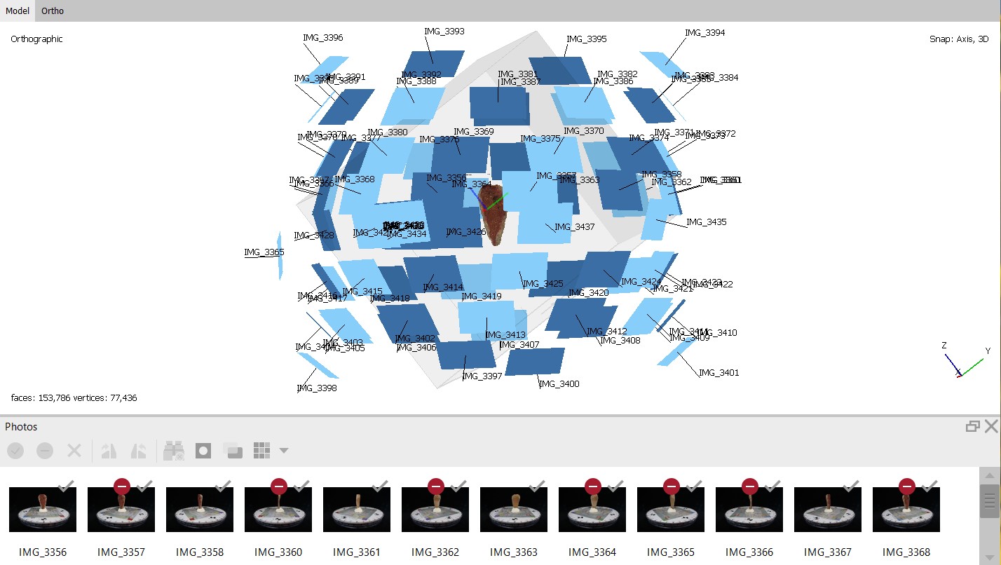
Can I create 3D models without a 3D scanner?
One of the main advantages of using a specialised 3D scanner is that it is quick to capture and process the data, but scanners can be very expensive. However, you can create a 3D model using only a digital camera and some processing software using a method called photogrammetry. It is quite time-consuming but when done correctly it can generate results with the same accuracy as a 3D scanners, with the added advantage that the model is in colour (referred to as texture in scanning). There are many resources with guidelines for doing photogrammetry on archaeological artefacts: check out Samantha Porter and colleagues’ paper with detailed instructions and scales you can download, and Dig Ventures also provides a step-by-step guide.
There are now apps that allow you to create models straight on your smartphone. New iPhone models with LiDAR allow you to create larger models of larger objects or landscapes, but it isn’t so easy to use or accurate for small artefacts like stone tools.
